

 About YTCO
 Facility & Equipment
 Quality & Environment
Board-to-Board Connections
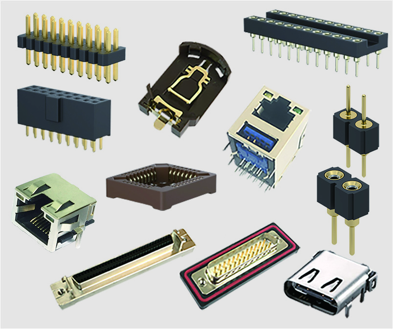
Stacked Boards: Pin headers and sockets connect two PCBs vertically or in parallel (e.g., Arduino main board and shield boards).
Modular Design: Functional modules are split across different PCBs and connected via headers/sockets (e.g., separating power modules from the main control board).
Modular Design
Replaceable Modules: Sockets are fixed on the main PCB, while pin headers are soldered onto modules for easy replacement or upgrades (e.g., sensor modules, Wi-Fi modules).
Test Interfaces: Pin headers serve as test points (e.g., JTAG/SWD debugging interfaces).
External Interface Expansion
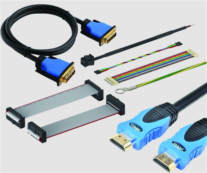
Cable Connections: Pin headers expose GPIO, UART, and other signals for use with jumper wires or IDC cables.
Standard Interfaces: 2.54mm pitch headers are used for IDE hard drive interfaces (early PCs), LCD displays (e.g., 1602 character LCDs), etc.
Jumper Configurations
Pin headers and jumper caps enable circuit configuration (e.g., selecting power voltage or communication modes).
Prototyping
Breadboard-compatible 2.54mm headers allow quick prototyping by plugging directly into breadboards.
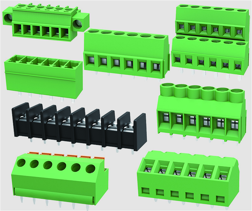
Pitch (Spacing)
Common pitches: 5.08mm、3.96mm、2.54mm , 2.00mm、1.27mm, 1.00mm—must match mating components.
Rows and Pin Count
Single-row (1×N), double-row (2×N), or multi-row options (e.g., 40-pin double-row for Raspberry Pi GPIO).
Mounting Styles
Vertical (Straight): Suitable for space-constrained designs.
Horizontal (Right-Angle): Used for parallel board connections.
Surface-Mount (SMT): Preferred for automated assembly.
Electrical Performance
Current rating (typically 1–3A per pin), voltage tolerance (e.g., 250V AC) must meet circuit requirements.
Mechanical Stability
Sockets with guide posts or locking mechanisms (e.g., FFC connectors) enhance stability.
Polarization (Keying)
Asymmetric pin layouts or notches prevent reverse insertion (e.g., USB connectors).
Poor Contact: Use gold-plated sockets or headers rated for high mating cycles (e.g., ≥10 insertions).
Reverse Insertion Damage: Implement polarization or mark orientation on the PCB silkscreen.
Misaligned Soldering: Use alignment jigs or opt for SMT headers.
Signal Interference: Shielded headers (e.g., high-speed board connectors) are recommended for high-frequency signals.
High-Density Applications: Replace with FPC cables or board-to-board connectors (e.g., BTB).
High-Speed Signals: Use coaxial or differential connectors (e.g., HSMC).
Due to their low cost and versatility, pin headers and sockets are indispensable in consumer electronics, industrial controls, IoT, and more. Proper selection enhances PCB design flexibility and reliability.